Network Architecture
This chapter helps you plan and implement MultiNode network(s) in EV charging installations. Read this chapter carefully to understand how various aspects affect network performance and installation efforts so you can select an appropriate MultiNode installation for your use case.
Before installation
- Plan your power supply and circuit breaker locations.
- Consider distances between devices; keep under 50 m per hop when possible. See Distance guidelines below.
- Decide if you need one network or multiple networks.
- Plan your load management approach.
Power supply considerations
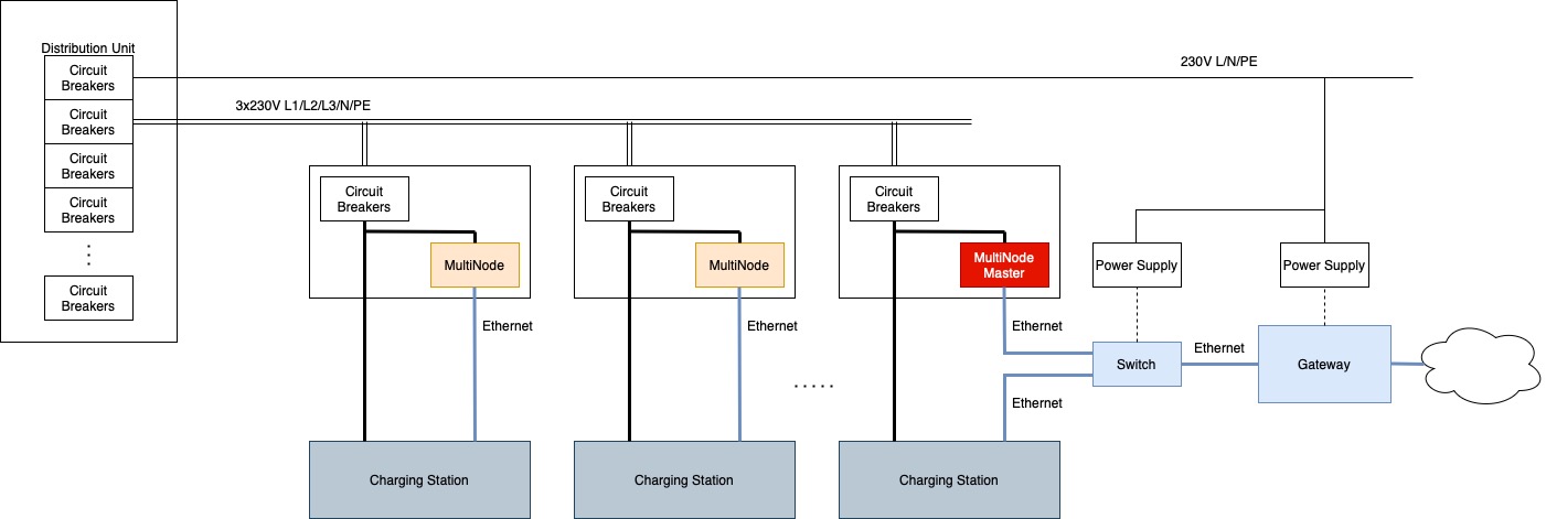
Circuit breakers: When using power rails, you need circuit breakers at each connection point. This lets you use thinner cables. You can use the same circuit breaker for both the charging station and MultiNode device, or give each one its own circuit breaker (see Single circuit setup).
Built-in power supply: MultiNode devices have integrated power supplies using L1/N terminals. Additional network components like switches and gateways need their own power supply. You can power them from the same electrical circuit or a different one (see Single circuit setup).
Independence from mains electrical power: PLC communication operates in the 2-50 MHz frequency range, which is separate from the mains electrical power.
Distance guidelines
MultiNode networks can span several hundred meters using built-in repeater functionality. Every MultiNode device automatically functions as a repeater when necessary, based on an underlying topology algorithm.
Per-hop distance recommendations
- Up to 50 m: Good performance
- 50-100 m: Potentially acceptable performance
- Over 100 m: Not recommended
Important: Line conditions may deteriorate over time, so plan conservatively.
Network architecture decisions
Single vs. multiple mains circuits
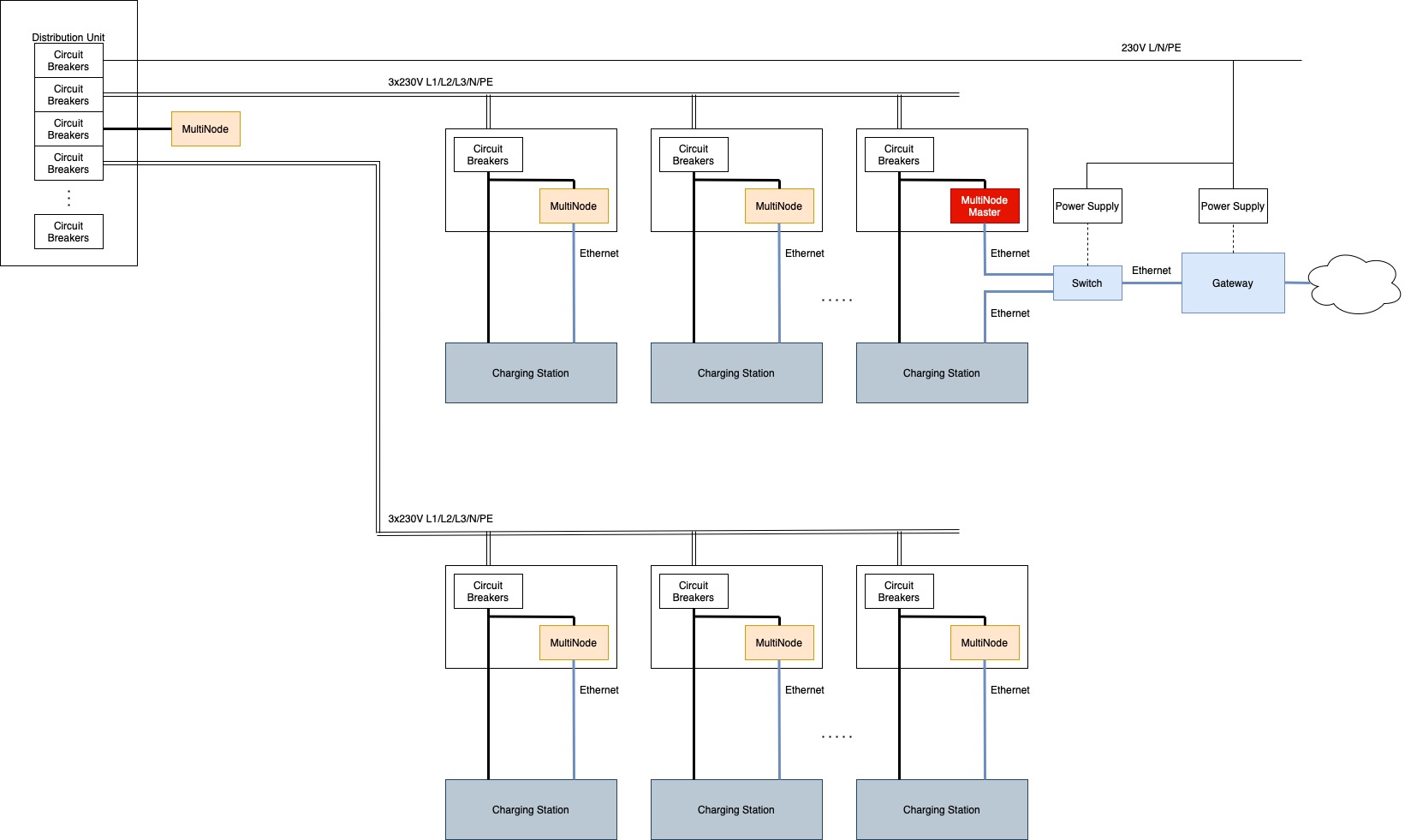
Single mains circuit (recommended) : A mains circuit is any cable or power rail connected to one circuit breaker. Best performance can be expectedwhen all devices operate on one three-phase circuit.
Multiple mains circuits: Possible but requires careful planning. The PLC signal must pass through distribution units, which can cause:
- Signal loss from multiple connection points
- Additional noise from various sources
- Impedance changes
Consider installing a repeater in the distribution unit on a separate, protected circuit (see Multiple circuit setup).
Network topology options
Option 1: Single large network:
- Spans multiple circuits through distribution unit
- May require longer signal paths
- Consider repeater placement (see Multiple MultiNode networks)
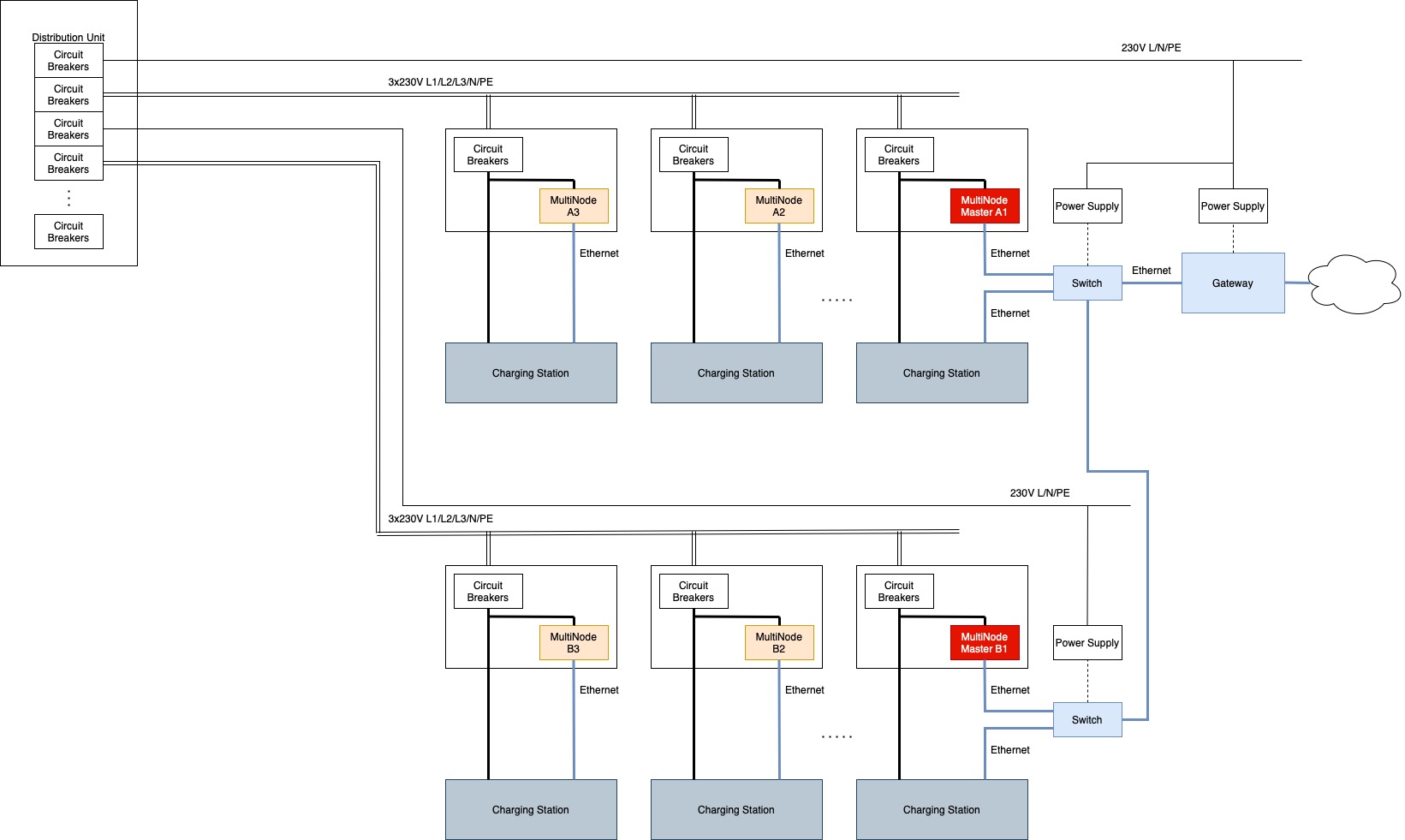
Option 2: Multiple smaller networks
- One network per circuit or floor
- Requires Ethernet connections between networks
- Avoids distribution unit signal issues (see Multiple MultiNode networks)
Master node placement
Both your electrical wiring and MultiNode network are arranged like a tree, branching out from one main point to all locations.
Your electrical system branches out from the main distribution unit. Your MultiNode network branches out from one master node to several regular nodes.
Important: The master node of the MultiNode network doesn't need to be in the distribution unit. If you can reach your network with Ethernet from another location, this is often better and avoids complications with the distribution unit.
Adding repeaters
As mentioned earlier, MultiNode devices automatically act as repeaters when needed. Supplement an existing MultiNode network with additional devices when:
- Per-hop distance is above 50 m
- Signal quality is poor
- You have long underground cables without tap-off options
Install additional tap-off boxes with circuit breakers for dedicated repeaters (see Multiple circuit setup).
Planning load management
MultiNode networks isolate regular nodes from each other — they can only communicate with the master node, not with each other. This affects how you plan load management.
Options for load management
Centralized management
Use a separate load management system in the building or cloud (see Centralized load management).
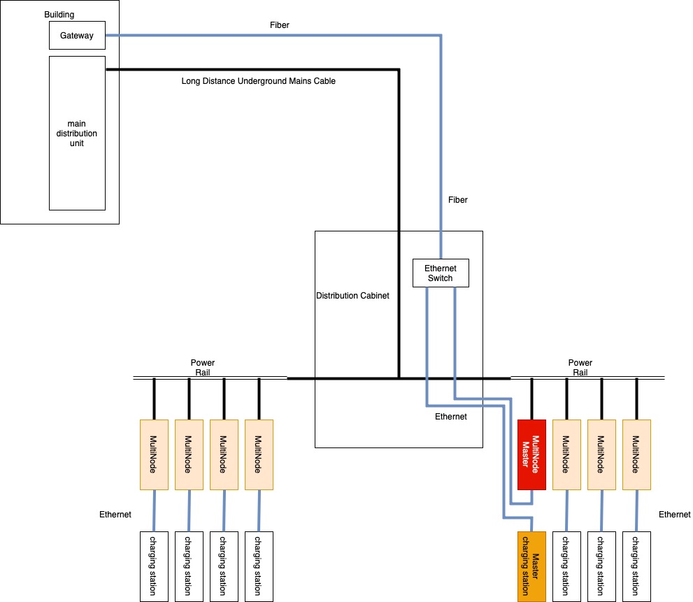
Master/Slave configuration
Use one charging station as the load management master (see Master/slave charging stations). Because of the network isolation, you need additional Ethernet cables so slave stations can communicate with both the master station and the gateway.
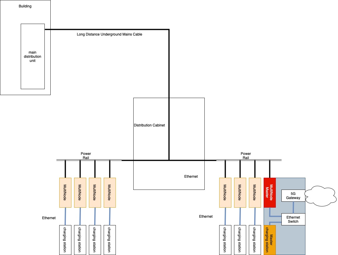
Alternative connectivity
If you use a mobile radio gateway instead of fiber, Mobile radio gateway setup shows solutions for both centralized management and Master/Slave setups. The setup may be simpler if your master charging station has built-in mobile radio or your gateway has a built-in Ethernet switch.
Common installation scenarios
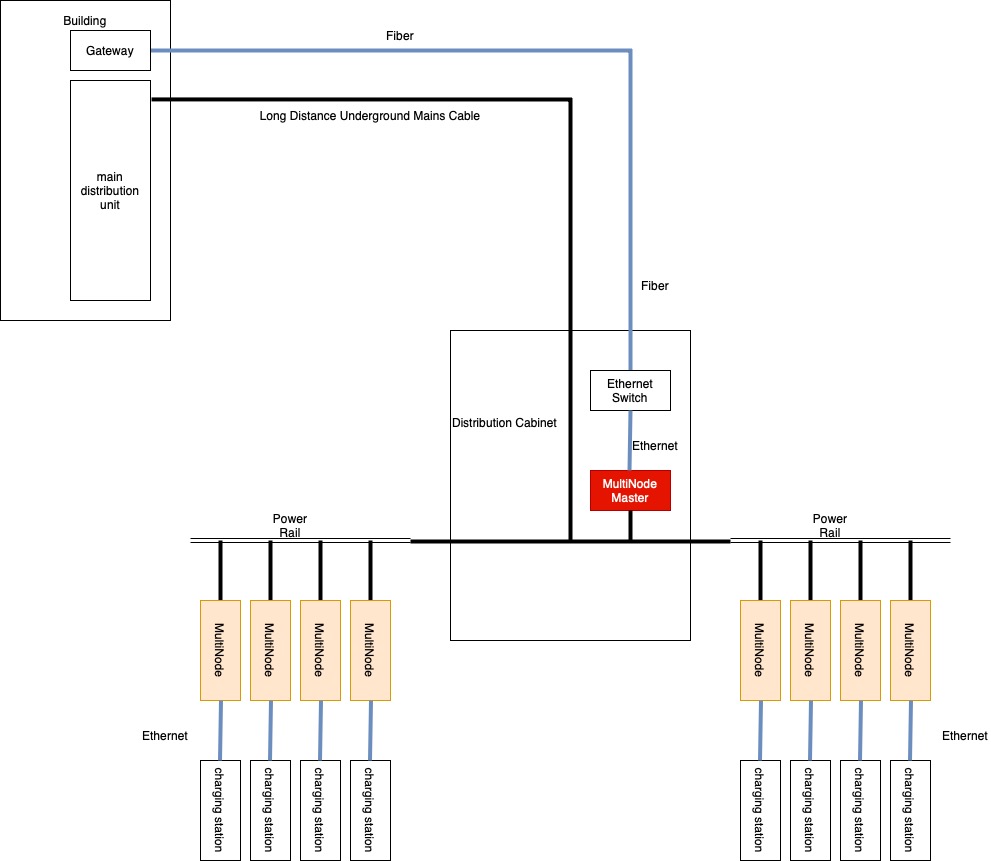
Outdoor car parks
For outdoor installations with power rails:
- Install distribution cabinet near power rail
- Run fiber cable in conduit alongside mains supply cable
- This avoids long-distance PLC connections (see Centralized load management and Master/slave charging stations)
Alternative: Use mobile radio gateway to eliminate fiber requirement
(see Mobile radio gateway).
Multi-floor car parks
Use separate networks per floor with vertical Ethernet connections between floors to avoid long PLC signal paths through distribution systems (see Multiple MultiNode networks).